ENEL STREET BOX CONTEST
September 2021
12 weeks
(300 hours)
Brief:
- Contains in a separated compartment a special terminal block and contactors (dimensions given)
- Contains in a separated compartment sensor for electrical and data measurements (dimensions given)
- Separated access between compartments, easy access for operators operations
- IP34D, louvers for cooling with natural ventilation, pin lock (burglar-proof lev. II UNI1627)
- Material: SMC, if metal then INOX, color RAL7001
- Well integrated in urban or rural context
- Respect principles of circular economy and sustainability
- Promote and enhance ENEL’s corporate image and vision through design
- Conveying messages addresses to the various stakeholders of the Company
ENEL
ENEL is an Italian multinational energy company and one of the main global integrated operators in the electricity and gas sectors. Established as a public body in 1962, it became a joint-stock company in 1992 and it was listed on the FTSE MIB index of the Milan Stock Exchange in 1999.
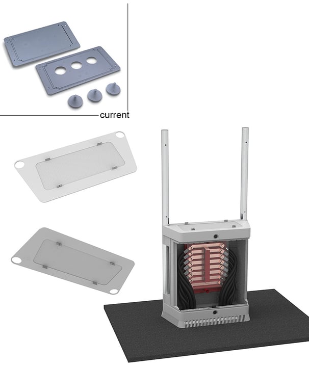
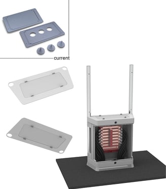
Concept
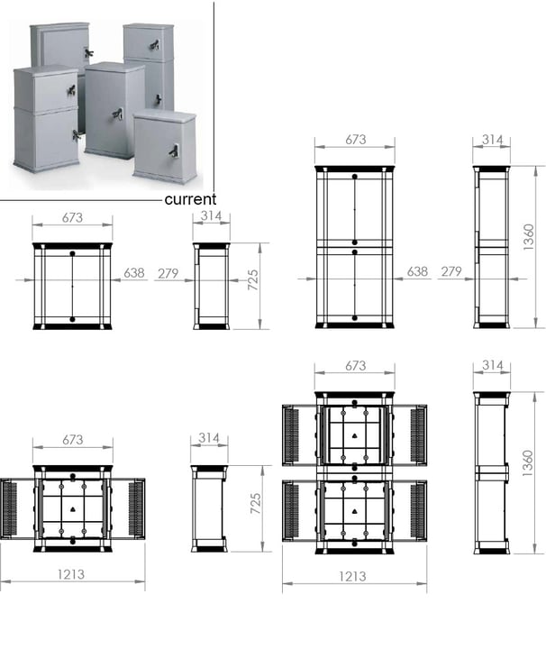
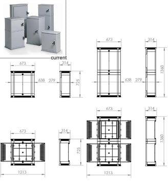
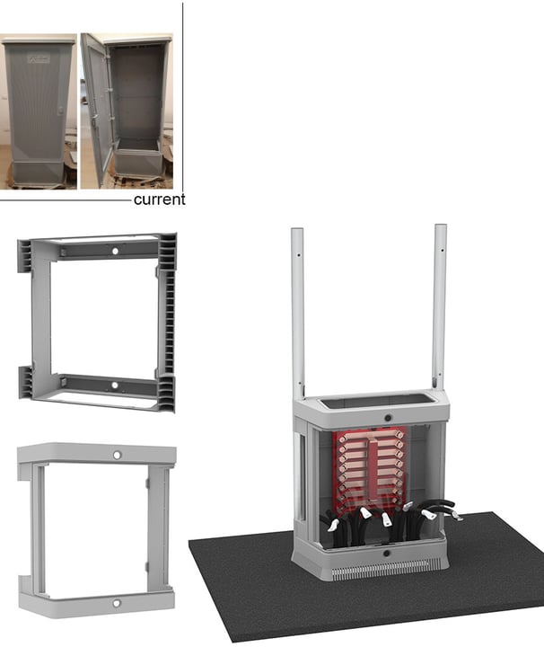
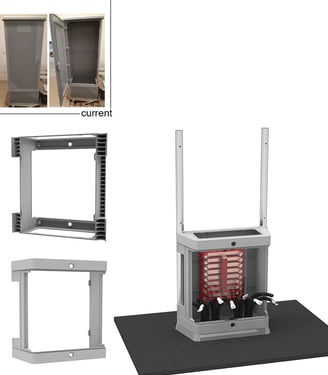
Current situation:
The actual cabinets are not modular and there is not possibilities for an upgrade if components are added later: In any case, it is mandatory replace the cabinet. There are therefore whole families of cabinets in many sizes and shapes to choose from according to requirements.
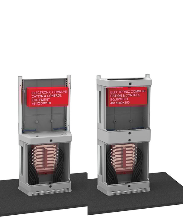
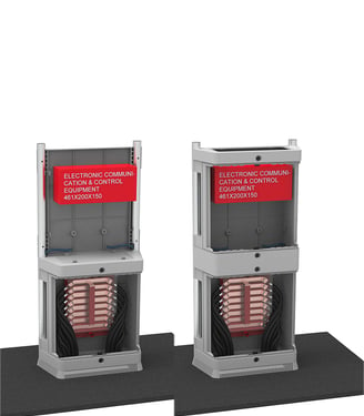
Proposed solution:
The proposed solution is a box consisting of modular compartments that has an upper and lower passage that allow modularity and upgradability. In this way, several compartments with different equipment e functions can be stacked. All these components can be assembled on site and can be easily covered with the ‘wrapping’ technique. Thus, this solution in scalable; it is possible to start with a single compartment and go up to three compartments (larger sizes are not recommended because they are uncomfortable for the operator).
1-compartment box height = 725mm
2-compartment box height = 1355mm
3-compartment box height = 1985mm
*2D Drawings realized with PTC Creo 8
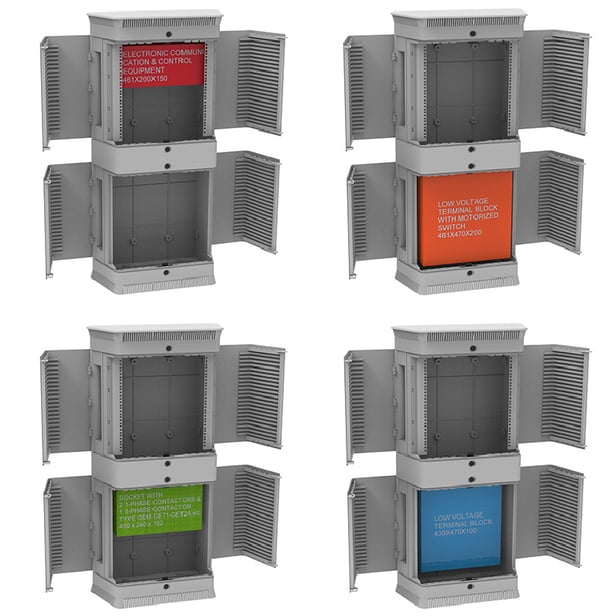
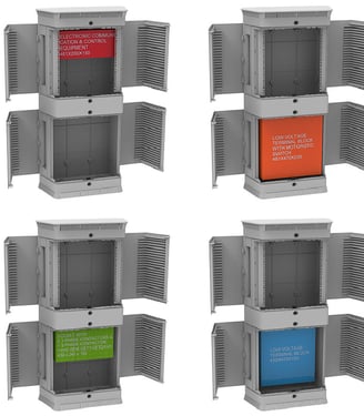
Concept
The cabinet is built during installation, first completing the lower parts and then the upper parts, making the operator’s work easier. The lower compartment is dedicated to terminal blocks and meters for cable saving and for simplify the installation. The 3d model study has been made considering the current terminal block with 16 copper cables of 95mm2 (the only one whose fixing points are known). The overall dimensions of the other devices given in the specifications has been verified. Note: The terminal blocks indicated in the specifications do not report fixing points but the space for adding new locations for nuts is considered. The upper compartment is dedicated to electronic communication equipment. The main idea is to fix the DIN rail to the rear but not knowing the quantities and lengths necessary, no fixings were made. Even in this case, however the protrusion of the nut seat was considered in order to have a support reference.
*3D Model realized with PTC Creo 8, render realized with Keyshot 11
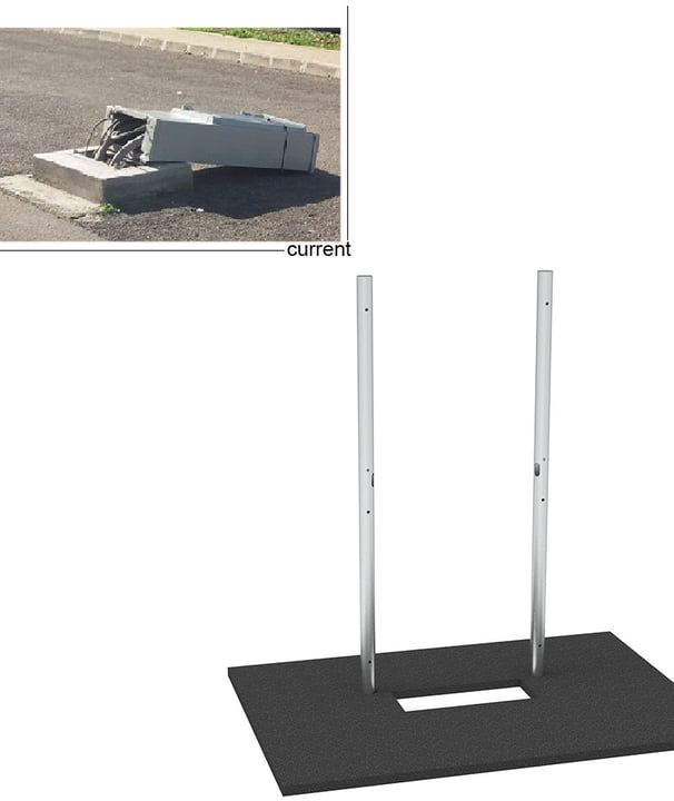
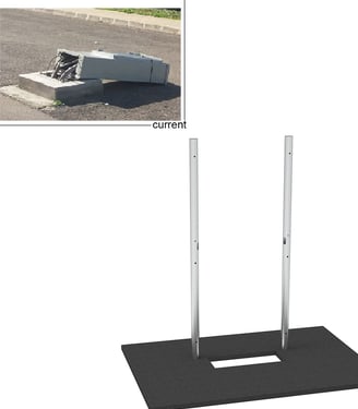
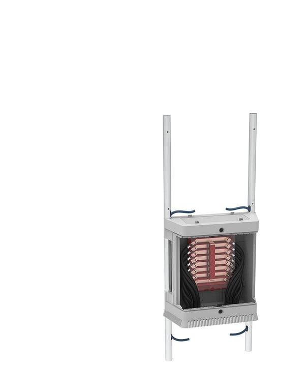
Ground Anchorage
Current situation:
The installation of the street cabinet involves the masonry of an anchor frame to which it is to be fixed. The frame has clamps about about 10cm long and therefore requires masonry work and the fixing of the box only at the base: for tall cabinets, this is often insufficient to keep the cabinet well anchored.
Proposed solution:
Drilling two holes and fixing two pipes in the ground (using a mounting template) we will have an easier fixing work and a greater impact resistance of the entire structure, especially if it is high. The tubes used have an external diameter of 48 mm and a thickness of 3 mm (Innocenti tubes), they are therefore standard tubes, available on the world market and very cheap. As required they can be in stainless steel or cataphoresis coated steel. They are easily machined by laser-cutting in case of additional holes.
*3D Model realized with PTC Creo 8, render realized with Keyshot 11
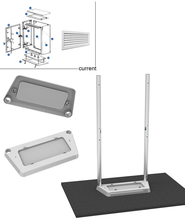
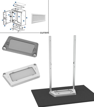
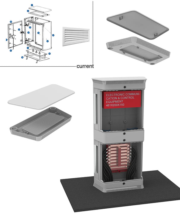
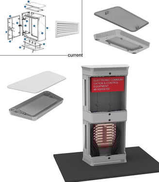
Foundation Component
Current situation:
To close the actual cabinets at the bottom and top are used thermoplastic panels (a different material). There is also a rich catalogue of other accessories, such as air vents, roofs, linths, supports, etc. that must all be purchased separately and have costs which, when added together, exceed the cost of the cabinet.
Proposed solution:
The foundation function, plinth function, air intake function and top labyrinth function has been concentrated in a single multifunctional element. Its main function is to create the foundation of the box in such a way as to guarantee water tightness from below and to allow the passage of incoming cables. The seal is guaranteed by the moulded channel for the housing of a flat gasket or oring. The second function it performs is that of a plinth: its height of 45 mm creates an elevation from the ground which allows the entire structure to be raised above the ground line. Water will be free to flow through it both in and outflow without creating stagnation. The third function it performs is that of air intake and labyrinth. In fact, the perimeter grating has a dimension minimum 2mm to meet the IP3X function, as do the internal holes, which have a minimum diameter of 2mm. The path from the perimeter cuts to the internal holes in itself creates a labyrinth that does not let water in.
*3D Model realized with PTC Creo 8, render realized with Keyshot 11
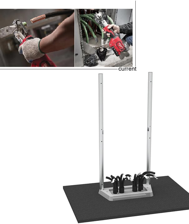
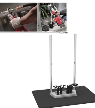
Power Cable Installation
Current situation:
The operator have a lot of difficulty to crimp the cable inside the pre-mounted box
Proposed solution:
The power cable are easy to install because the operator work outside the cabinet structure and the cable crimping operations are simplified.
*3D Model realized with PTC Creo 8, render realized with Keyshot 11
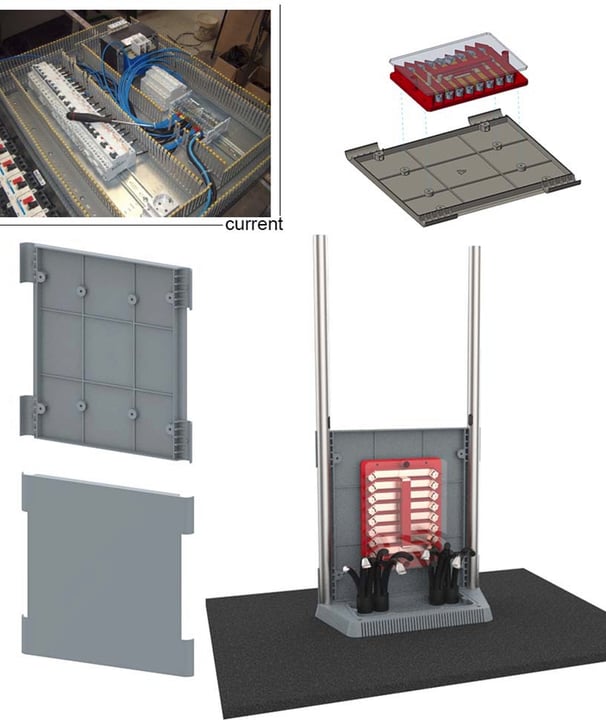
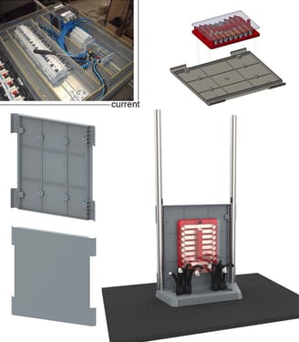
Power Compartment - Rear Component
Current situation:
Often, especially when working with din rail modules, a panel is fixed to the bottom of the cabinet, on top of which the electrical components are fixed. This bottom panel in fact allows all electrical equipment and wiring to be pre-assembled on the bench, simplifying the physical construction of the circuit and thus reducing installation time. Once completed, it is then inserted pre-assembled into the cabinet, completing the installation by connecting the incoming and outgoing cables.
Proposed solution:
The rear component of the cabinet also serves as a panel on which all the components can be pre-assembled. In this way, at the installation site the pre-assembled bottom will be easily positioned on the structure and installation time will be saved. Knowing the fixing distances of all the devices to be installed, all the fixing points can be molded on the rear, so that any type of realization can be fulfilled. Unfortunately, the fixing points were not known and therefore only the fixing of a known terminal block was realised on the model.
*3D Model realized with PTC Creo 8, render realized with Keyshot 11
Power Compartment - Front Component
Current situation:
The current cabinet structure is composed by several parts bolted together, it is pre-assembled and then sent to its final destination. The internal electrical components are installed inside the assembled cabinet on site.
Proposed solution:
The front component of the new cabinet is assembled on site with 4 snapfits, saving time for assembly and saving space for transportation.
*3D Model realized with PTC Creo 8, render realized with Keyshot 11
Snap-Fits
Current situation:
In the current structure, the various panels are fixed with self-tapping screws and threaded inserts embedded in the mould. The latter are not easy to separate from the SMC in the disassembly phase, creating a problem of material purity in the recycling chain.
Proposed solution:
In order to easy insert and remove all the component are connected with snapfits. In this way, assembly times are drastically reduced, assembly equipment is eliminated, and finally recycling is simplified thanks to homomaterial components.
Septum Divider
Current situation:
For the transition from one compartment to another in the current cabinets, dividers are used, which are different for each type of box.
Proposed solution:
With the overlapping of several compartments, a separating septum with the locations for the nuts has been created in the same logic of the box. In fact the septum have 4 snapfits on top and 4 on the bottom. The thickness is minimal (2mm) to simplify the drilling operation in case of cable passage. In order to guarantee the air passage and the IP34 between compartments, a lot of 2mm holes are positioned on the septum.
*3D Model realized with PTC Creo 8, render realized with Keyshot 11
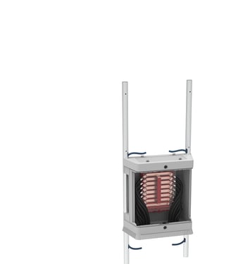
Low Voltage Cables Installation
In order to reach the upper low-voltage compartment, low-voltage cables must pass through the compartment with power cables, which causes electromagnetic interference that disturbs and distorts electrical signals. Normally this problem is remedied by using shielded low-voltage cables, although proximity to power cables does not completely solve the problem.
If the cables, on the other hand, pass through another metal conduit, additional shielding will be provided by the conduit itself, allowing for more effective electromagnetic protection. By passing inside the two tubes, which will be previously perforated by means of laser-cutting, the cable will be able to enter the tubes directly from the shaft below. The cables will exit directly into the upper compartment through a second cut in the pipe.
*3D Model realized with PTC Creo 8, render realized with Keyshot 11
LV Compartment - Rear and Front Components
Current situation:
Often, especially when working with din rail modules, a panel is fixed to the bottom of the cabinet, on top of which the electrical components are in turn fixed. This bottom panel in fact allows all electrical equipment and wiring to be pre-assembled on the bench, simplifying the physical construction of the circuit and thus reducing installation time. Once completed, it is then inserted pre-assembled into the cabinet, completing the installation by connecting the incoming and outgoing cables.
Proposed solution:
The rear component of the cabinet also serves as a panel on which all the components can be pre-assembled. In this way, at the installation site the pre-assembled bottom will be easily positioned on the structure and installation time will be saved. Knowing the fixing distances of all the devices to be installed, all the fixing points can be molded on the rear, so that any type of realization can be fulfilled. Unfortunately, the fixing points were not known and therefore only the fixing of a known terminal
Foundation & Roof Component
Current situation:
To close the actual cabinets at the bottom and top are combined thermoplastic panels (a different material). There is also a rich catalogue of other accessories, such as air vents, roofs, linths, supports, etc. that must all be purchased separately and have costs which, when added together, exceed the cost of the cabinet.
Proposed solution:
The same foundation can also be used to perform the same function on the upper area of the box. It can be connected with the same snapfits with all other parts of box.
The upper air intake and labyrinth function is the fourth function integrated in the foundation component as the perimeter grating with a minimum size of 2mm and the internal holes with a minimum diameter of 2mm also form a labyrinth path for an IP34. This means that water will be able to enter the vertical cuts, both top and bottom, but will slide away through the same cuts without entering the (2mm) holes of the bottom component. This impenetrability is ensured by the different height of the holes in relation to the position of the cuts, which makes this passage impossible.
*3D Model realized with PTC Creo 8, render realized with Keyshot 11
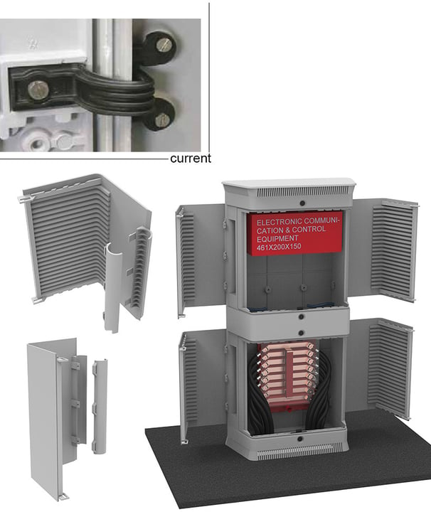
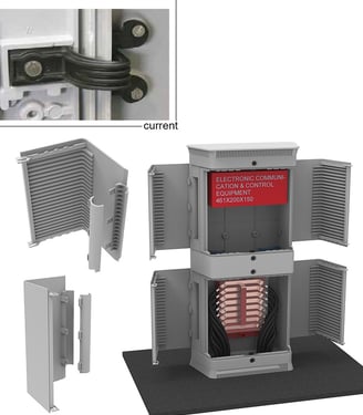
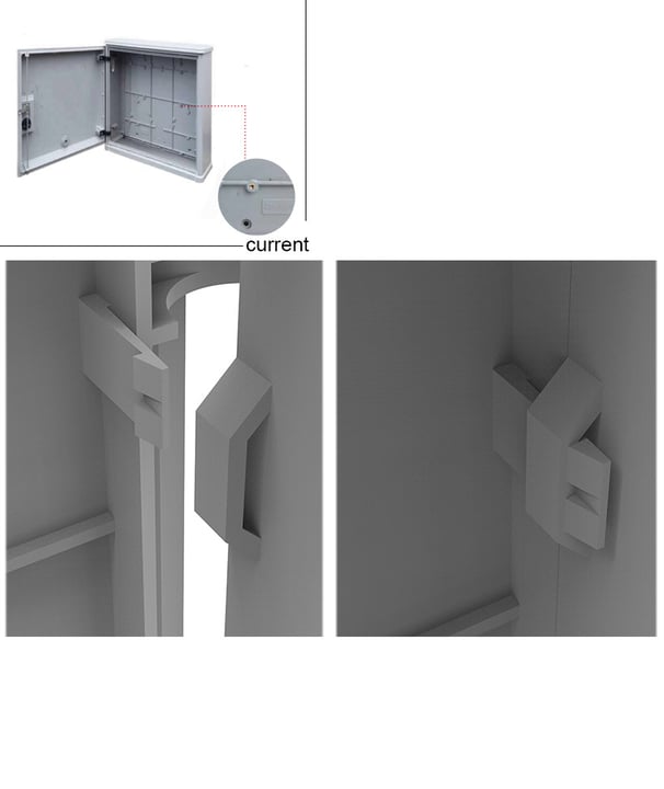
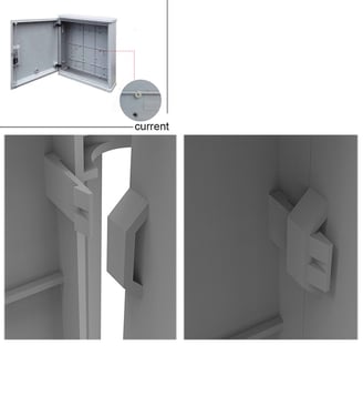
Door & Clamp Components
Current situation:
Currently, the doors are connected to the cabinets by means of thermoplastic hinges (a different material from the box) fastened with self-tapping screws. The hinges offer a limited opening (90°), are often subject to breakage because they are made of a material that is not very resistant (mechanically and atmospherically) and finally they are made of a different material to be recycled when being decommissioned.
Proposed solution:
The hatch consists of two parts: the door and a C-shaped rod. The material is homogeneous of the whole box. It is fixed to the tube around which it rotates, it opens 115° and thanks to its shape leaves more space for the operator. It is connected with 3 snapfits.
*3D Model realized with PTC Creo 8, render realized with Keyshot 11
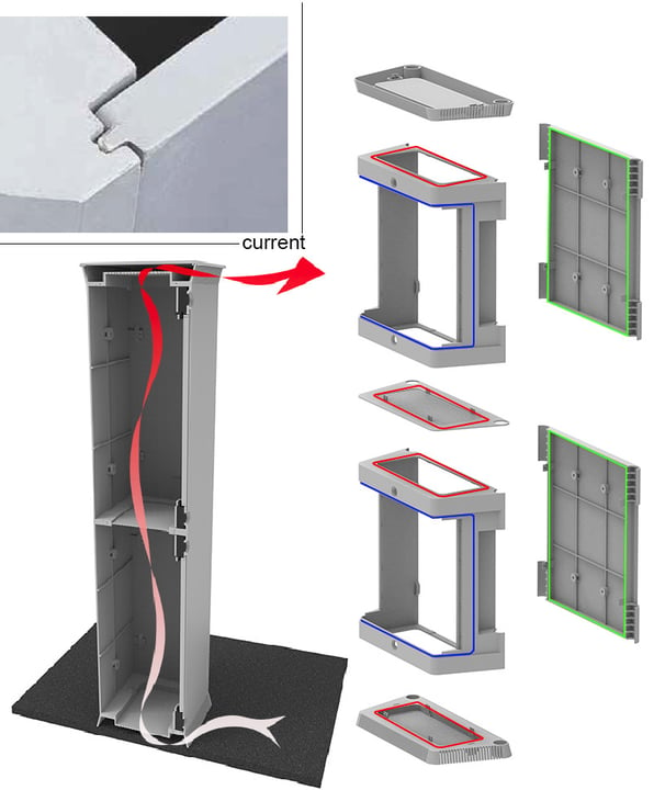
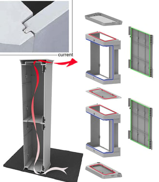
Gaskets
Current situation:
Current IP44 enclosures are constructed with an interlocking between the various panels that guarantees the IP rating. However, in the upper area where the labyrinth for the air intake is located, a gasket is used to ensure tightness.
Proposed solution:
The adjacent surfaces between the frontal and rear component are perfectly level and it is therefore easy to obtain the same indentation (green) as the current. Between the lower and upper window of frontal component, and between the frontal component and the foundation component two slots have been created in order to accommodate the gasket (red). There are two possibilities: the flat gasket or the oring. Between the frontal window of the frontal component and the doors a groove is realized in the mould in order to accommodate another oring (blue). The door will press against the oring, sealing the inner area. It should be noted that the area subject to IP34 is to be considered only inside the box, where the orings ensure water impenetrability. This means that water will be able to enter the vertical cuts of the foundation component, both top and bottom, but will slide away through the same cuts without entering the 2mm holes. This impenetrability is ensured by the different height of the 2mm holes in relation to the position of the cuts, which makes this passage impossible. The air will have free access thanks to the ‘chimney’ effect whereby the air heated by the internal electrical units tends to rise and exit at the top, thus creating an internal vacuum that draws in cooler air from below.
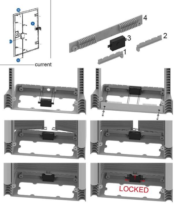
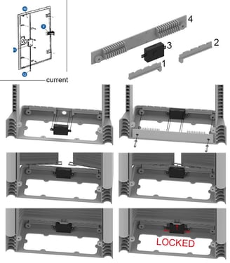
Door Locks
Current situation:
To close the current cabinets, there are a number of components, different for each type of door, which block the opening of the door at 2 points: at the top at the bottom. They are made in different shape (one for each type of door), they are made in different materials and they are fixed with different types of screws.
Proposed solution:
To ensure a very strong compartment closure and also to guarantee the correct compression of the seal on the doors, the locks on each compartment are doubled, one above and one below. The door locking system can be pre-assembled or can be installed when the box is complete: it is designed to simplify maintenance. On the left and right side of the key block, the two rods called Block (1) and Block (2) are positioned. The key block, commercially available with the code SC-YS (3), is then positioned by inserting the 4 pins in the Front component and inserting the two lateral pins of the Blocks 1 and 2. It is all interlocked, without screws. The component that mechanically block all components is the Holder (4), which will be fixed to the Front with 2 snapfits.
The indentations in the door and the locks are circular indentations that originate in the center of rotation of the door. When the keys are in the open position, full spaces and gaps in the Blocks (1)(2) coincide and the doors can be opened. When the doors are fully closed, actuating the key block releases three tongues (14.5 mm gap). The lateral one slide the locks sideways into a position that stop the movement of the two doors. The third tongue of the key block, engages the pair of slots in the doors, locking them centrally. In this way, the doors are locked on the hinges, they are locked on both the upper and lower horizontal line, and are finally joined
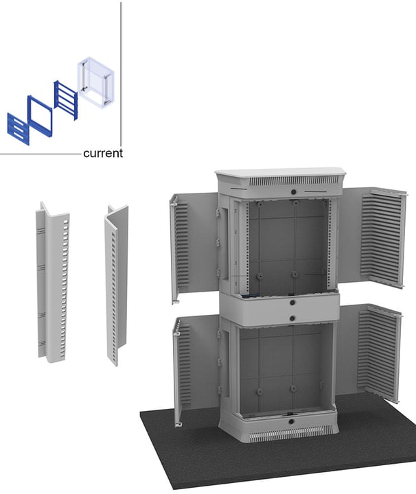
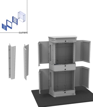
Rack 19" Supports
Current situation:
In order to be able to insert 19″ rack elements, a series of brackets are currently provided for mounting inside the box. These are different components in different materials.
Proposed solution:
An adapter has been realised, which is symmetrical and it can be tilted and installed on both internal side panels of the Front component. This adapter is fixed to the central component with snapfits and offers the possibility of installing 10 19″ units. In the figure, as required by the specifications, the 19″ adapters are mounted on the upper compartment (used as a control instrument compartment)
*3D Model realized with PTC Creo 8, render realized with Keyshot 11
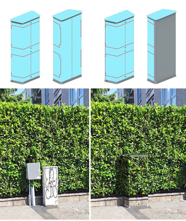
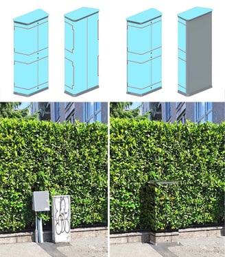
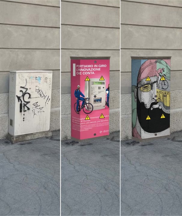
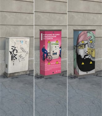
Wrapping
The outer surface of the box has been deliberately left very smooth so that it could be covered with wrapping, a modern technique that covers objects with printed films (widely used for cars). In this way it is possible to camouflage the box in the target environment or to communicate with users or stackholders. The print will already include the triangle signal and the e-distribuzione company logo. If wrapping is not desired, the triangle signal and the Enel logo can still be glued individually. The film can be applied in the central area and on the roof: it is applied in its entirety with close cabinet, in this case a rectangle of 1260mm x 1681.4mm (2.118m2), and after cuts are applied (in red) in the openings. This is the same method of applying wrapping to cars but in this case the orthogonality and a clean, regular geometry of the surfaces help to facilitate the operation.
Boxes are often located very close to the walls of houses. If in this case there is no need to cover the rear wall (not visible and difficult to access) the wrap can only be applied to the front wall and the roof, resulting in this case a rectangle measuring 1260mm x 995mm (1.209m2). Examples of “camouflage” wrapping are in the pictures, where the existing background was photographed before installation and was reproduced on the film in order to integrate the box in green surroundings.
*Images realized with Adobe Photoshop CC 2018
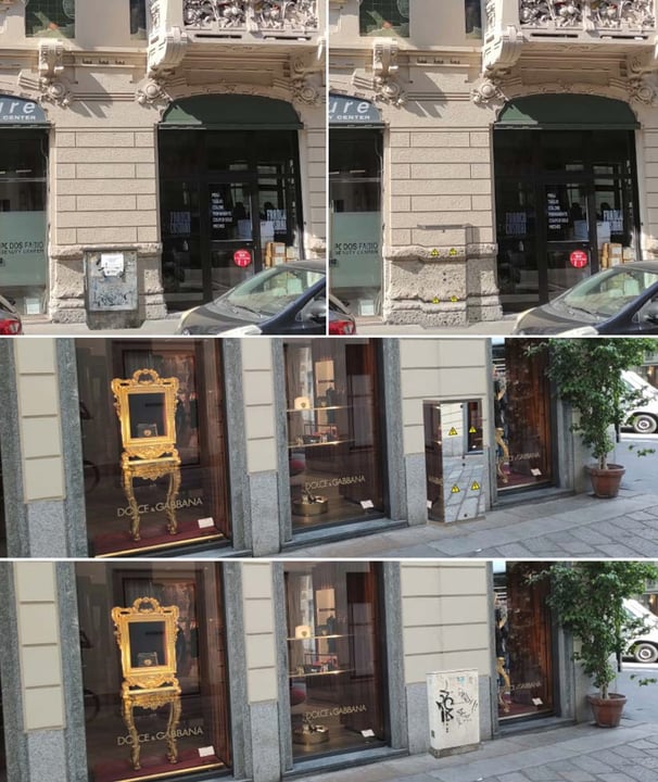
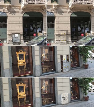
Wrapping
Other examples of “camouflage” wrapping are in the pictures, where the existing background was photographed before installation and was reproduced on the film in order to integrate the box on historical buildings. The film can also be made mirror-like, which is useful in fashionable city contexts.
*Images realized with Adobe Photoshop CC 2018
Wrapping
Finally, the film can simply be a vehicle for an advertising message or it can become a space for street artists, as happened in the ‘Cabine d’Autore’ or ‘Cabine in Rosa’ projects. In the latter case, the painting of the street artist will take place on the film before it is applied, thus also opening up the possibility of reproducing the work.
*Images realized with Adobe Photoshop CC 2018
The path behind this solution: Design For Six Sigma pathway...
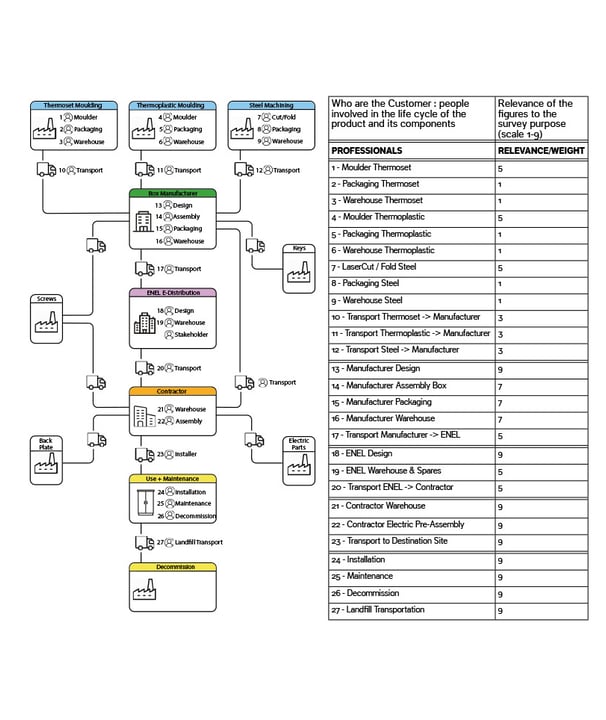
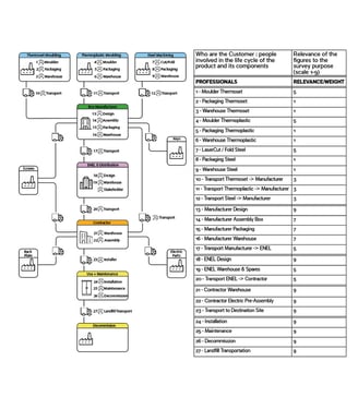
VOC (Voice Of Customer). Identification of Customer Segment
The first step is to identify all the people involved in the life cycle of the product and its components.
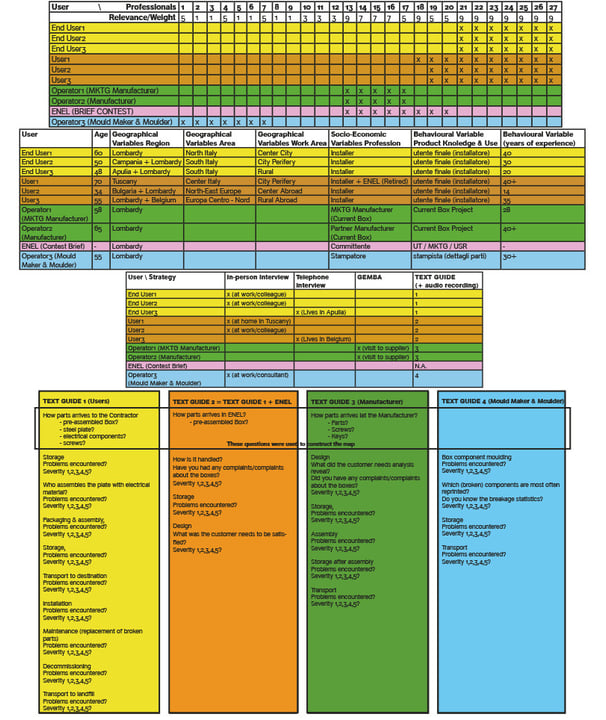
VOC Sample Selection & VOC Plan
The sample to be interviewed was chosen on the basis of working knowledge:
Colleagues with experience in this work but also directly involved suppliers (main actors in the current supply chain).
The first matrix correlates the chosen persons with the professional figures listed on previous slide. All the professional figures in contact with the box (or parts of it) have been identified (at least the figures most relevant to the survey).
With the colours, stratifications were created by differentiating the users by work experience, with the aim of finalising the collection of information by focusing on specific experiences.
In the second matrix has been evaluated the segmentation of the sample with respect to the market: by geographical / socio-economic / behavioural variables.
In the third matrix has been reported the choice of interview strategy (choice ‘forced’ by logistical problems) : in-person interview, telephone interview and GEMBA (on site)
In the fourth matrix has been prepared the outline of an ‘experiential’ interview where following a time-sequenced narrative it's possible to make the user relive the experience mentally, bringing out all the problems encountered.
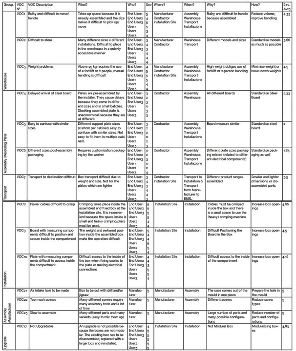
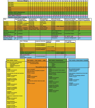
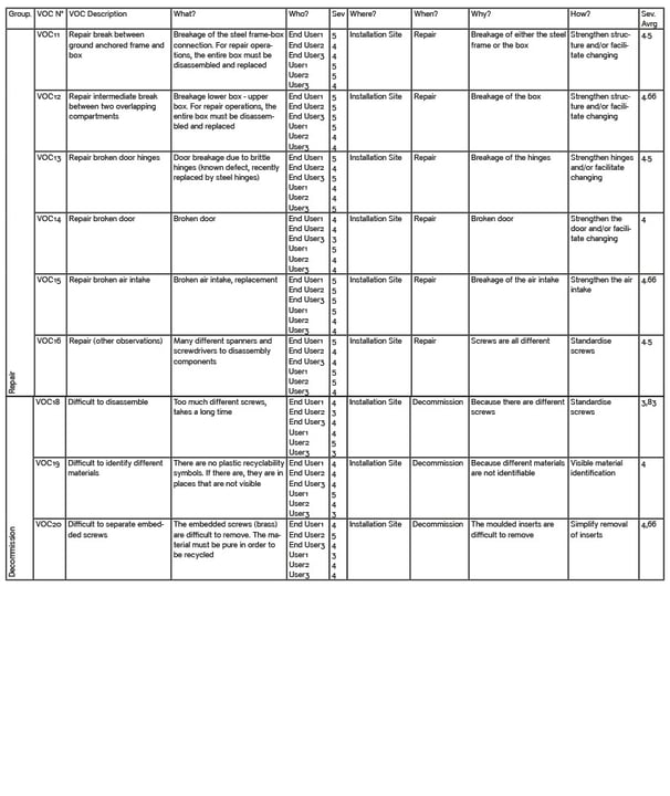
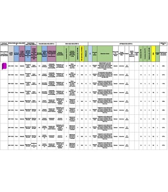
VOC Table (5W+1How)
These are the VOC emerged from the interviews with the importance ratings attributed by the various users. The "Where" and "When" refer to the life cycle on previous slides.
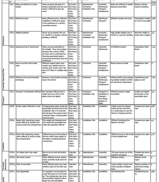
VOC Table (5W+1How)
These are the VOC emerged from the interviews with the importance ratings attributed by the various users. The "Where" and "When" refer to the life cycle on previous slides.
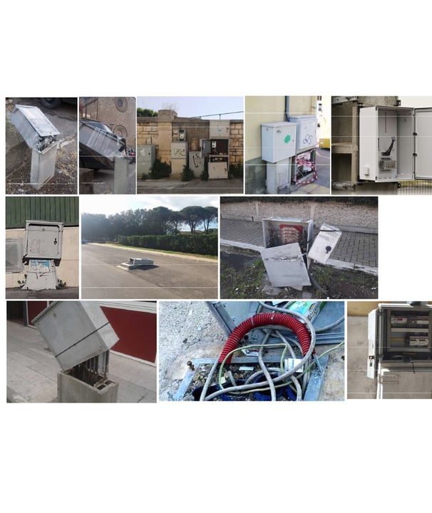
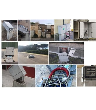
Implicit Technical Requirements (observation)
The box must not break down.
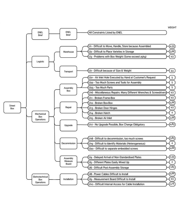
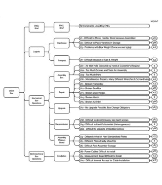
VOC Tree
The VOCs were grouped into categories. The weights are the average of the weights assigned by the users surveyed.
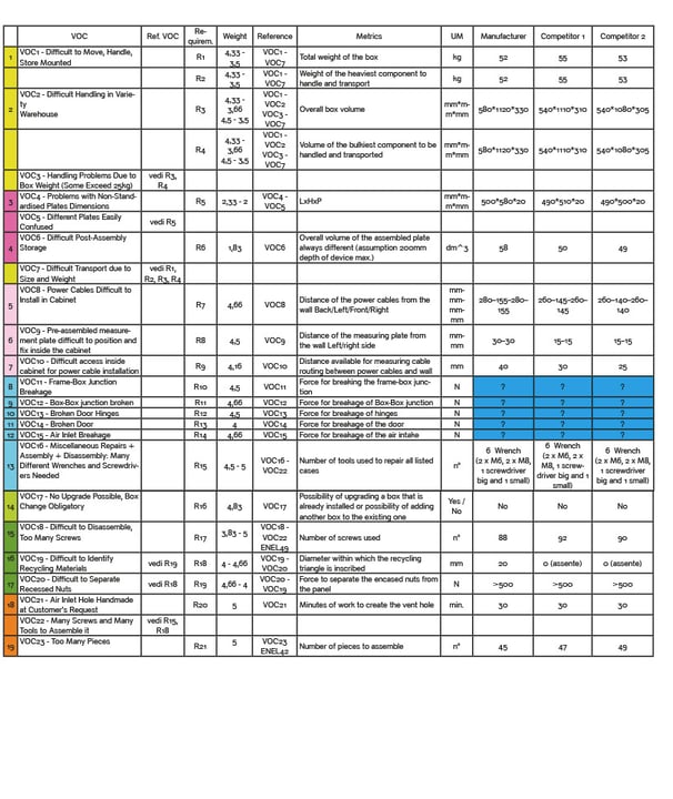
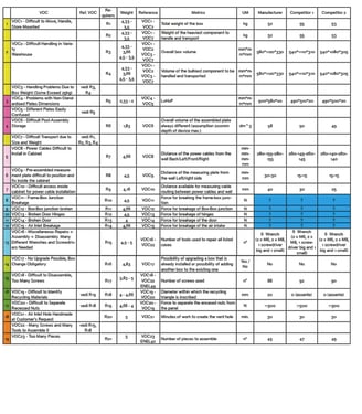
Definition of Requirements & Metrics
Manufacturer Box and 2 other competitors has been compared (with data collection).
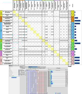
VOC Prioritisation with AHP (Analytic Hierarchy Project) & Coherence Verify
There were too many VOCs and in order to reduce their number as well as to choose the most significant ones, AHP prioritisation has been used.
Using ‘SuperDecision’, the consistency index of the matrix has been calculated, which being below 10% confirms the consistency of the matrix.
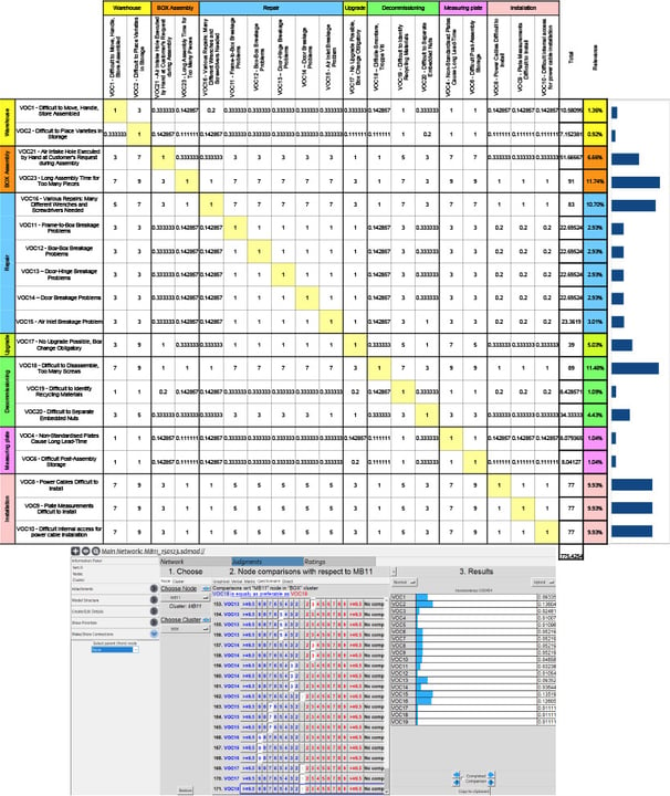
QFD (Quality Function Deployment) House 1
Manufacturer Product VOCs has been valued (value 1-2-3-4-5) and compared with competitor products.
CTQ (Critical To Quality) requirements were reported in the centre of the QFD House 1 by valuing (1-3-9) their relevance to VOCs.
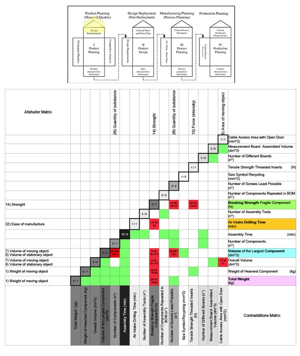
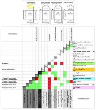
QFD House 1 Analysis of Interactions + TRIZ (Theory of Inventive Problem Solving) Analysis
In the roof of QFD House 1 the numbers of the diagonal indicate how many positive and negative (contradictions) interactions are present for each requirement. The colour in shades of grey is consequential.
After filling the “QFD roof” with the coherences in green and the contradictions in red, the items that most represented the contradictory needs were searched for in the Atshuller matrix. TRIZ is a problem-solving methodology that aims to foster innovation and creativity; It provides a systematic approach to identify and overcome contradictions or obstacles in order to generate inventive solutions. The resulting items were placed on the other two sides of the roof and the red squares were filled in with the numbers from the matrix.
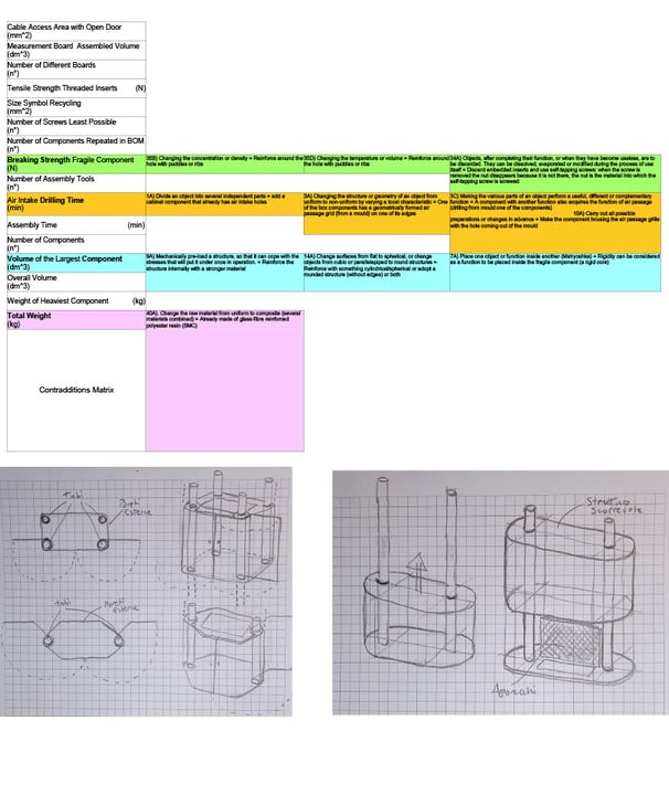
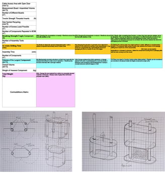
TRIZ
Reading through the various descriptions on the right-hand side are the “abstractions” applicable to the project.
Highlighted in bold are some “ideas” that the descriptions have triggered.
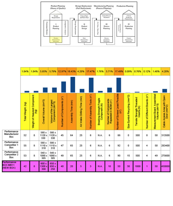
QFD House 1 : Results
In the last line, the performance targets of the new box are set, and at the top are the characteristics and their weight percentages.
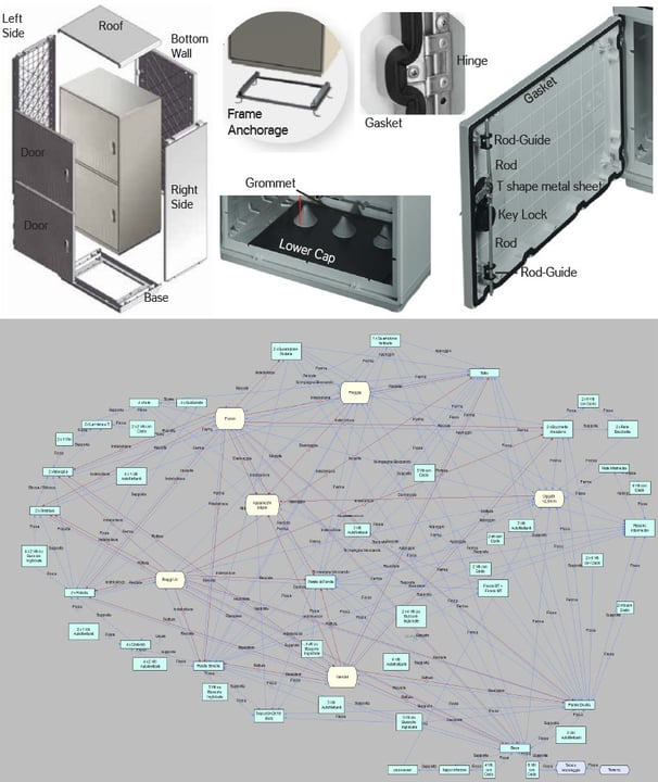
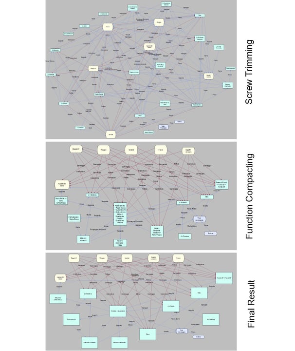
Function Analysis with TechOptimizer
Starting from the rising ground, the structure has been analysed based on the Manufacturer product. All components of the Box are linked in order to understand how is made the product and what are the funcions of components.
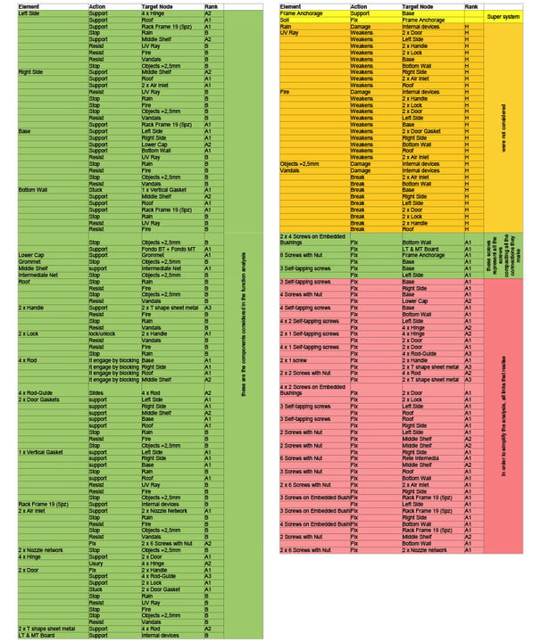
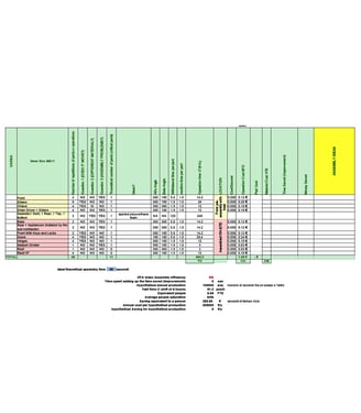
Function Analysis with TechOptimizer
The Function Table showing the components, their functions, the target node they address and the rank, the higher the closer to the target.
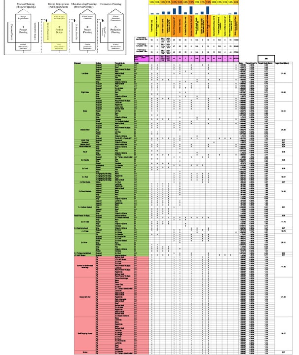

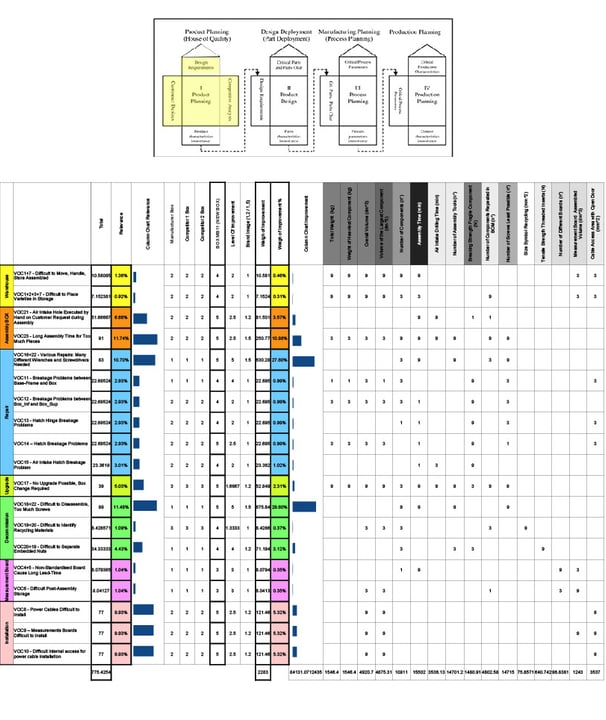
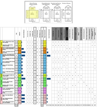
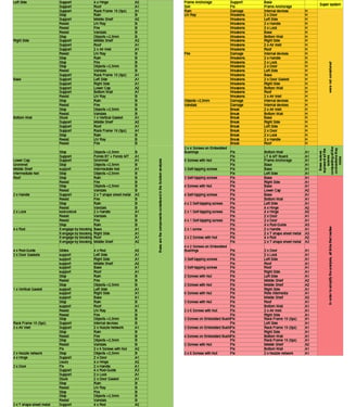
QFD House 2 : Value Analysis
By reporting the components and their functions (from the function table just seen) in QFD House 2, their effectiveness (1,3,9) in achieving the objectives of QFD House 1 (in pink) was assessed.
Importance and Adequacy, both current and desired, has been assigned a value (1,2,3,4,5).
By allocating the total cost (300 Euro, target cost) to the various functions, the maximum cost of each function and component has been finally calculated.
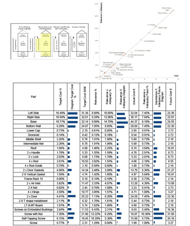
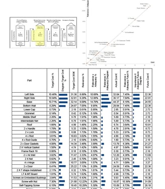
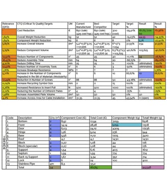
QFD House 2 : Value Analysis
Here we can see the data summarised for each component, giving a more immediate reading.
On the side is the graph relating Importance x Adequacy to Cost, where you can see that an imbalance is taking place with the door seals.
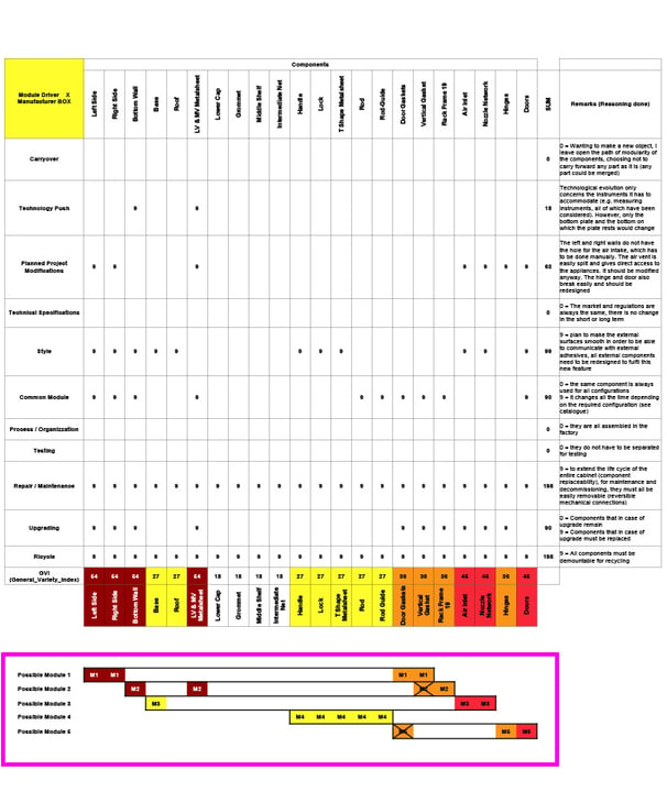
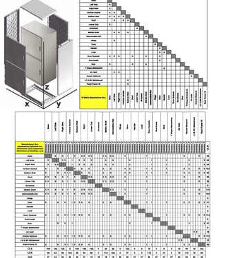
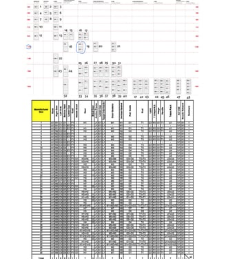
MIM (Module Interface Matrix) Manufacturer Box
In the matrix of Manufacturer Box, the parts and their readiness to follow the modularisation or standardisation criteria (called ‘drivers’, grades 1,3,9) are highlighted.
Their sum is the General Variety Index.
The higher the GVI, the more the component is a candidate for modularisation.
The lower the GVI, the more the component is a candidate for standardisation.
In the lower box a possible unification of the components for creation and modules
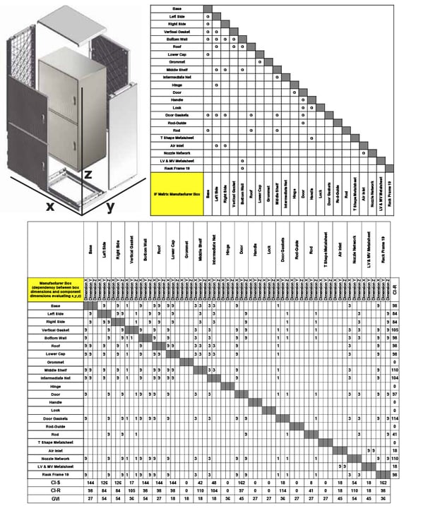
Interface Matrix Manufacturer Box
The upper matrix highlights the fact that we are neither in the presence of a Bus Modular architecture (called ‘Pizza’ or Base Unit Assembly, all components on the diagonal) nor of a Full Modular architecture (called ‘Hamburger’ or Modular Assembly, with all components on the vertical) (G=Geometrical, E=Energy).
In the lower matrix, since all interface relations are geometric, the three dimensions x,y,z were entered and the interdependencies were valued with values 1,3,9, assigning 1 to the least plausible links and 9 to the most plausible ones.
This matrix thus makes us understand the relationship between the change in box dimensions and the change in component dimensions

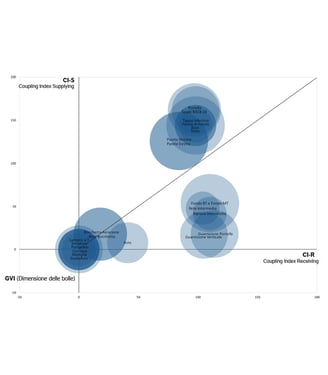
Interface Matrix Manufacturer Box
With the bubble graph you can see that some elements are on the axis intersection. These are the standard components that never change (hinge, handle, rod guide etc). On the bottom right we have the “bullied” components that are subject to change by the other components. At the top are the “bully” components, which impose the changes.
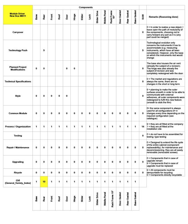
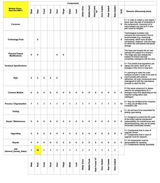
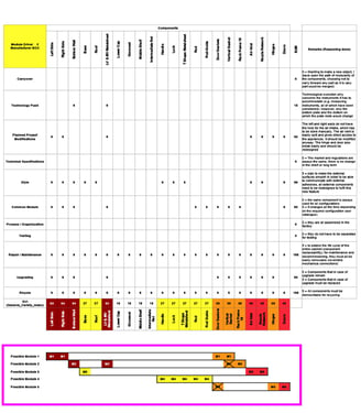
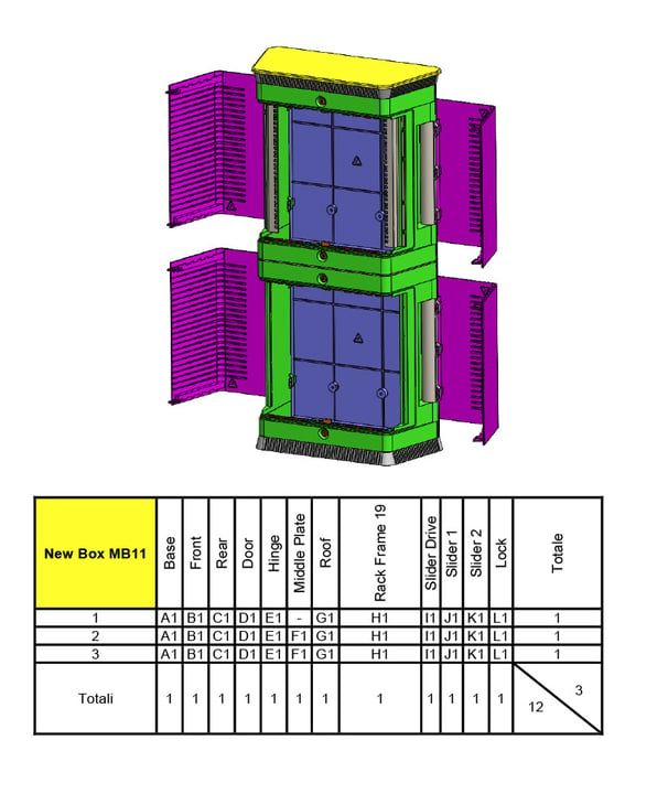
MIM (Module Interface Matrix) New Box
The matrix has been recreated with the new box idea, compacting functions in the way explained in MIM Manufacturer Box slide. The box designed in this way has the weak point on the devices to be inserted in the box: when a new device comes out with new fixing points, we will have to modify the basic component. (NB: all the appliances on the market have already been considered and it is not a sector that has frequent innovations).
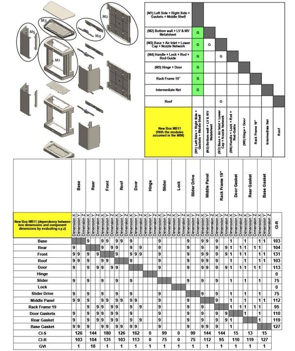
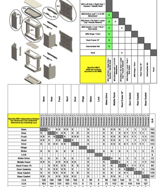
Interface Matrix New Box
If we look at the concept created through the possible modules of the MIM analysis, we see that there is a central component on which all other components are in contact. The gaskets are all on the central component.
Similarly to what was done before, since all the couplings are geometric, the three dimensions x,y,z were entered and the interdependencies were valued with values 1,3,9, assigning 1 to the least plausible ties and 9 to the most plausible ones. This matrix thus makes us understand the relationship between the change in box dimensions and the change in component dimensions.
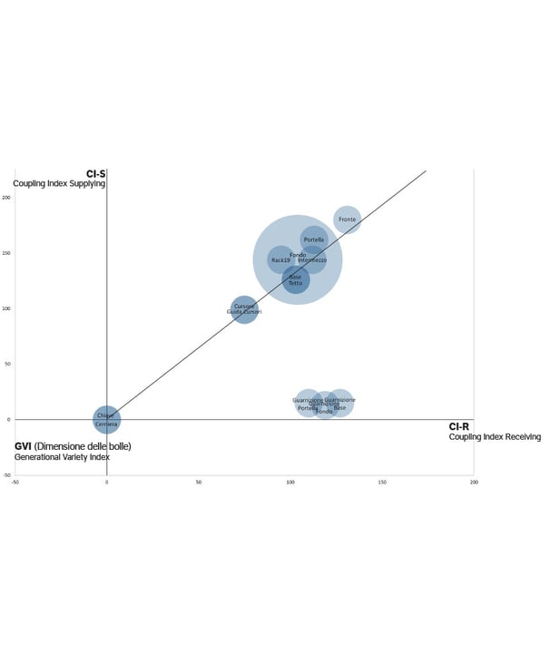

Interface Matrix New Box
With the bubble graph, you can see that some elements are on the intersection of the axes. These are the standard components that never change (hinge, key). At the bottom right, on the other hand, we have the “bullied” components that are subject to the changes of the others (gaskets). In fact, these are subject to the variations of the front, the only component in which they are inserted. Finally, on the diagonal are all the other components, equally bullied and bullied, which are more balanced with respect to the functions they perform.
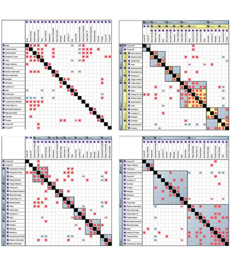
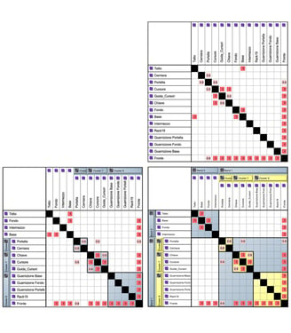
DSM (Design Structure Matrix) Analysis Manufacturer Box
Using the CAM2 software, the relationships between the components has been analyzed and assigned as follows:
- 0 (empty) if there is no contact between two components (3 DOF).
- 0.3 if between two components there is contact but there are 2 DOF.
- 0.6 if between two components there is contact but there are 1 DOF.
- 1 if between two components there is contact and there are 0 DOF.
From the initial matrix (top left), studies has been carried out to understand through clustering what to modulate and what to standardise.
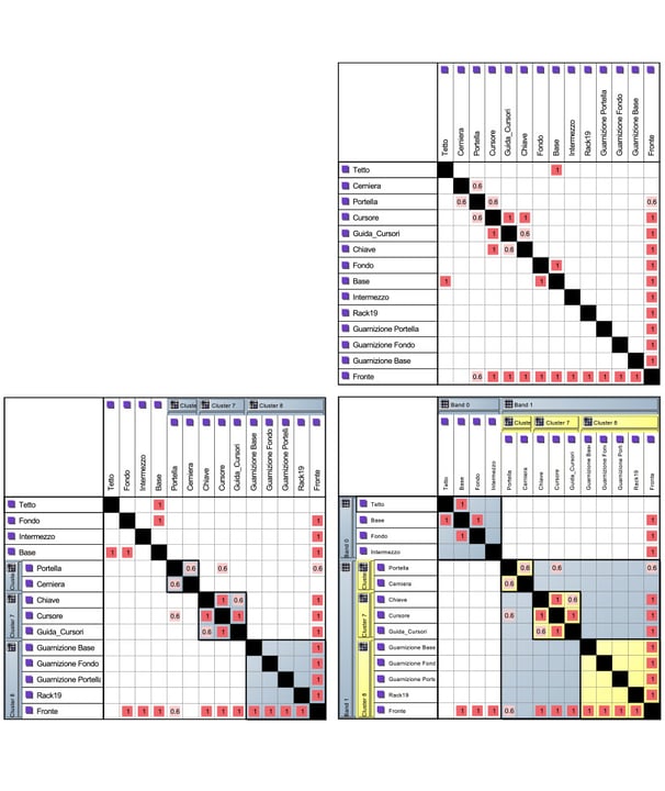
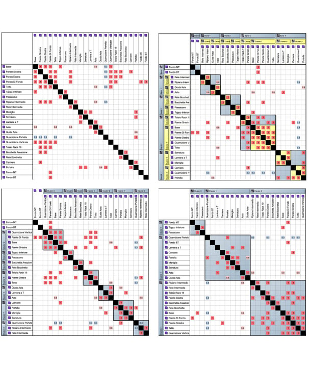
DSM Analysis New Box
Using the same software, the new box components has been analyzed and assigned as follows:
- 0 (empty) if there is no contact between two components (3 DOF).
- 0.3 if between two components there is contact but there are 2 DOF.
- 0.6 if between two components there is contact but there are 1 DOF.
- 1 if between two components there is contact and there are 0 DOF.
From the initial matrix (top left), studies has been carried out to understand through clustering what to modulate and what to standardise.
No improvement is expected
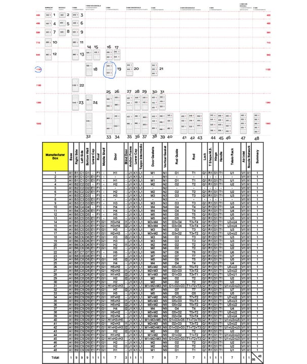
Variety Reduction Program : Variety Index for Manufacturer Box
By analysing the Manufacturer catalogue, a matrix can be made to identify the components they use. The Variety Index is the number of parts (86) multiplied by the number of product varieties (48). In this case, the Variety Index is 4128

Variety Reduction Program : Variety Index for New Box
Analysing the concept realised, we can calculate the Variety Index by multiplying the number of components (12) by the number of product varieties (3). In this case the Variety Index is 36
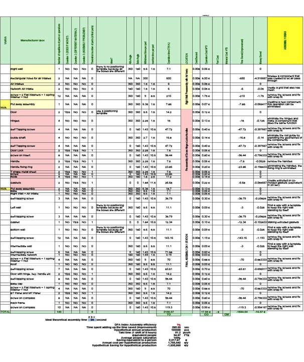
DFA (Design For Assembly) Manufacturer Box
The analysis considers the ideal need of the component by evaluating it on the 3 questions (0=all NO, 1=at least one YES), after which based on the alpha and beta symmetry as well as the size of the component, according to the Boothroyd tables (p. 83,84) a positioning and insertion time is established.
You can see the two pre-assemblies: in yellow that of the right wall (to be drilled by hand for the installation of the ventilation grille), in red the door.
The ideal theoretical time (on the 8 minimum theoretical parts) is 24 sec.
The theoretical assembly time on the 143 parts is 2140 sec = 35.5 min.
A production of 100kpc/year requires 35 full-time people.
The ideas for reducing time are:
1) Create a component that allows air to pass through.
2) Eliminate screws by replacing them with snap-fits.

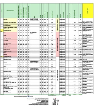
DFA New Box
Using the same system, the new concept has been evaluated. A pre-assembly can be seen, after which the idea is to have the box assembled on-site by the installer (see belown)
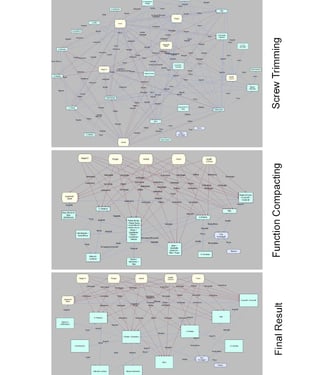
Trimming with TechOptimizer
By means of the formula F^2/(P+C) where F is the rank of the function, P the rank of the penalty and C the cost, the trimming suggestions are obtained.
First, all screws were eliminated as revealed by the previous analyses, with the idea of replacing them with snapfits.
Functions were then merged into a number of components, as already revealed in the MIM analysis, achieving maximum simplification.
Finally, the blocks and the relationships between them were concretised.
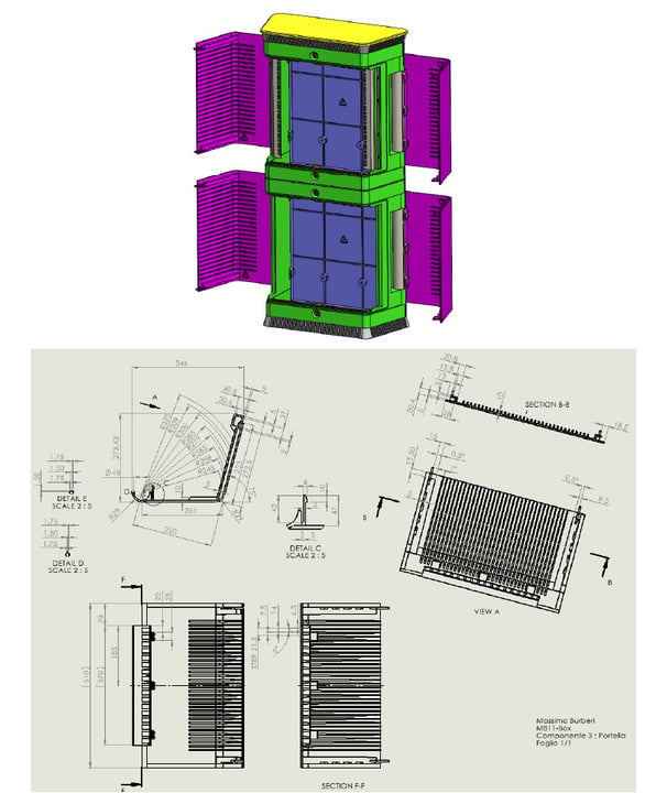
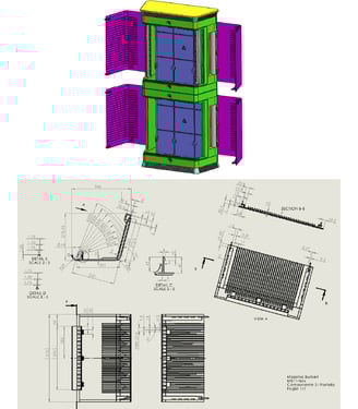
Models and Drawings
The 3D model of each component and the overall assembly has been realized.
Drawings of all components were then produced without the critical tolerances.
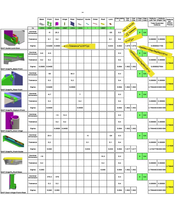
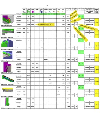
Tolerance Analysis
In order to define all critical tollerancies, all snapfits and all critical splice points has been analysed individually and as a whole.
Playing with Tolerance and Cp, the best combination was calculated to achieve zero defects per million and the minimum Cp which simplifies production while also decreasing the cost of the component
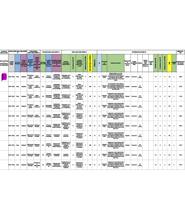
FMEA Analysis
Since the structure and components are therefore already defined, we move on to the FMEA analysis.
The analysis revealed the criticality of the door component.
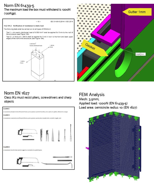

FMEA Analysis: Door weaknesses
Risk of break-in with screwdriver.
The hatch at 4mm from the outer wall has a 1mm drainage channel for water that would seep in at the junction of the hatches.
The water that would seep in would meet the gutter and coagulate, flowing to the lower end of the hatch and then out the area protected by the gasket.
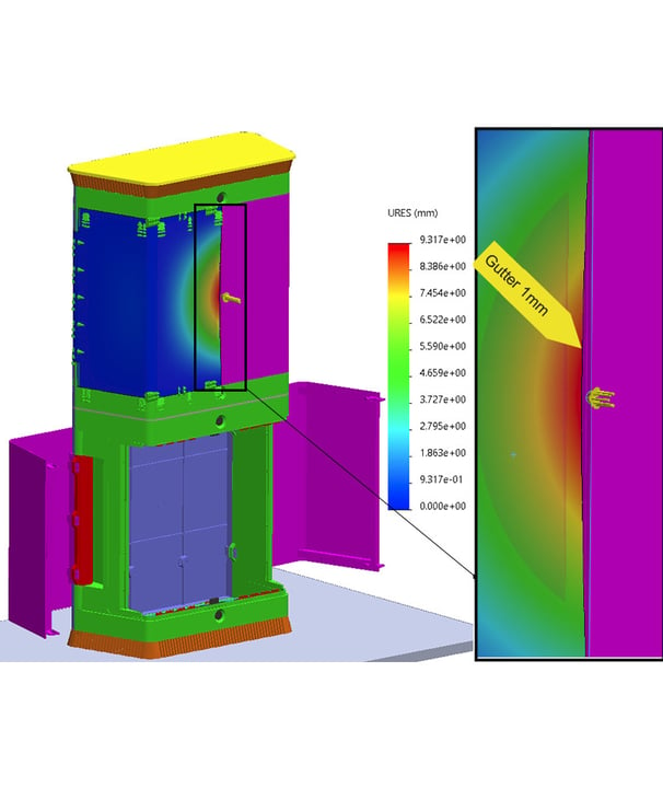
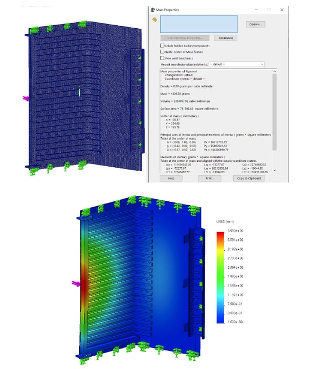
FEM (Finite Element Method) Analysis:
The door WITHOUT NERVATURE gave a negative result.
The calculated deformation is 9.3mm, not enough to penetrate but enough to reach the groove.
If the screwdriver reaches the groove it can leverage to further deform the door.
DOE (Design Of Experiment):
DOE's aim in this case has been to minimise weight and minimise door deformation with the right combination of ribs.
The ribs have width W, height H and distance between them D. The 2 dimensions for each parameter lead to 2^3=8 trials.
Each configuration determined a weight P
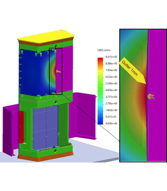
FEM Analysis:
8 models has been analysed.
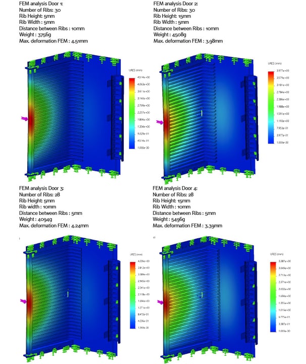
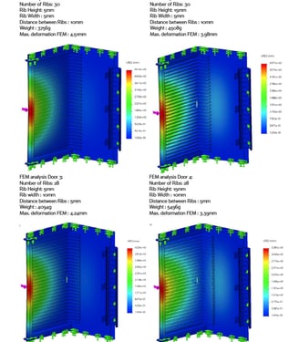
FEM Analysis:
8 models has been analysed.
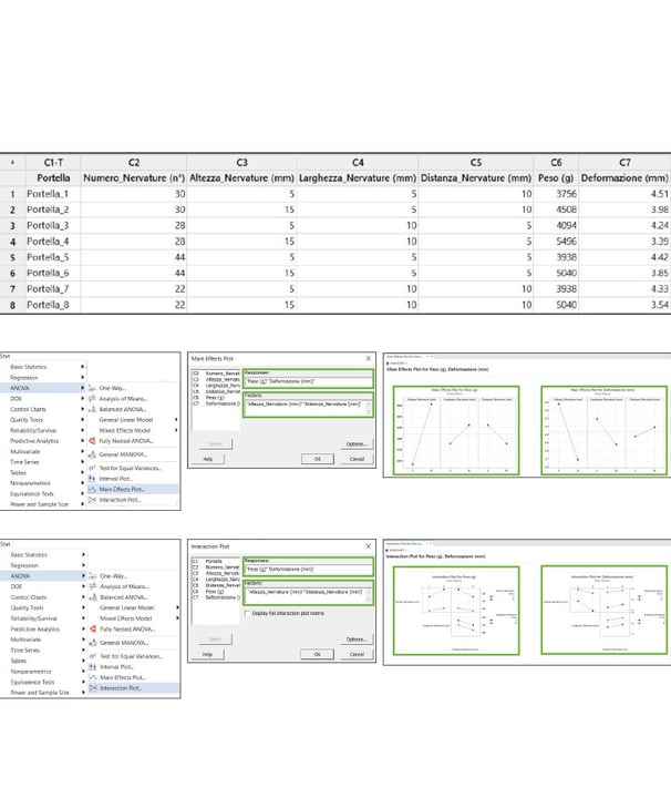
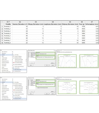
DOE Door with Minitab
The collected data were entered and analysed with Minitab.
With the Main Effect Plot, we can see that all selected variables (Width, Height and Distance of the ribs) impact both Weight and Deformation.
With the Interaction Plot we can see that for the Weight we expect Height-Width and Height-Distance interactions, while for the Deformation we expect Height-Width interactions
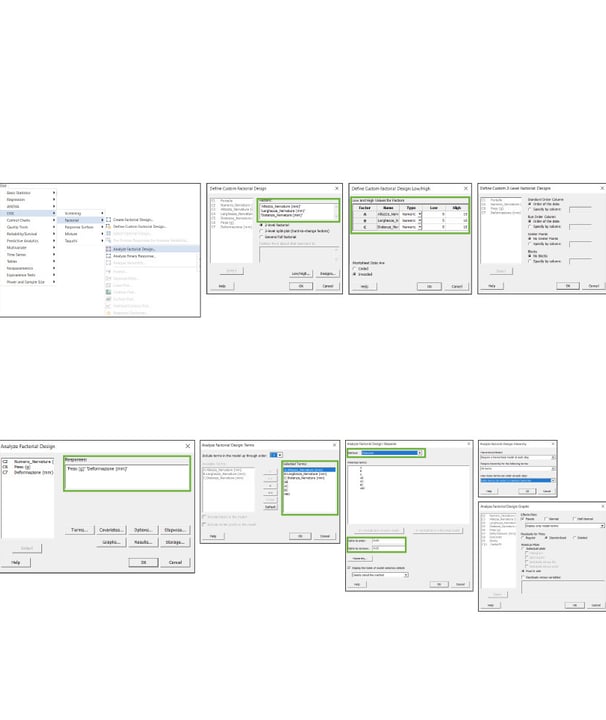
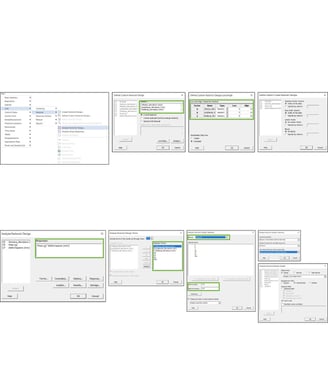
DOE Door with Minitab
With the Factorial DOE, the factors (Height, Width, Distance) were entered and the two variable levels set (leaving everything else as default).
Responses (Weight and Deformation) were then set, all variables and their combinations were entered into Terms, and finally the Stepwise was activated (which cuts the result to 15%)
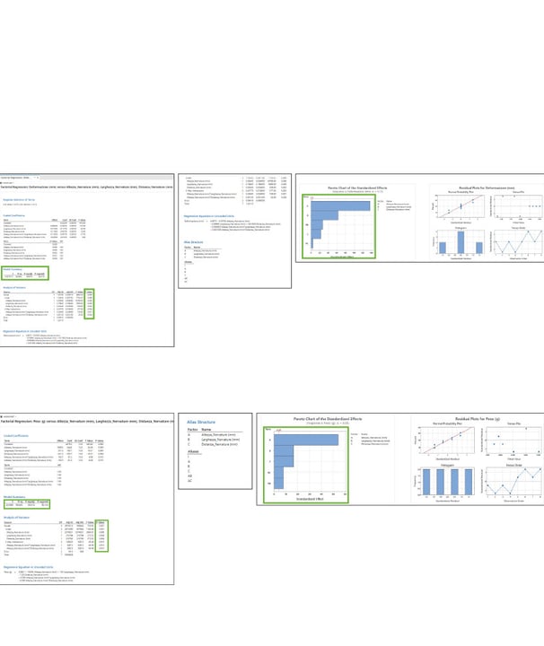
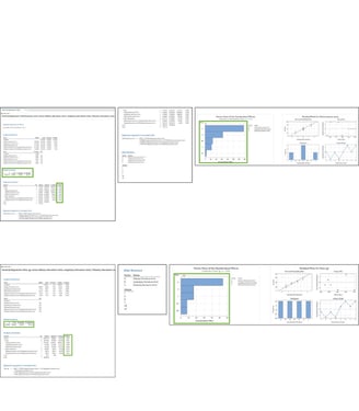
DOE Door Results
In the DEFORMATION result, we find that all variables (which passed the stepwise cut) are significant, including the interactions Height-Width (AB) and Height-Distance (AC). This can be deduced from the PValues all <5% and the Pareto reporting all variables as significant.
The Rsq at 99.99% is excellent, as is the Rsq predicted at 99.87%.
In the WEIGHT result, all variables and all significant interactions are present. This is evident from the low PValue <5% of all variables and the Pareto reporting of all variables as significant.
Note that however Rsq is high (99.94%) as is Rsq predicted (99.12%).
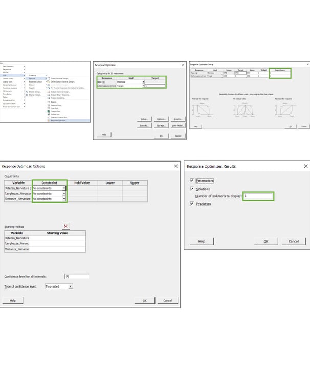
DOE Door Optimisation
Finally, the final optimization was launched.
The Goals of Weight Minimisation and Deformation Target at 4mm were requested. The Importances of the two targets has been left at 1 (equally important).
It was then chosen not to impose any fixed value for any variable.
Finally, 1 possible solution was requested.
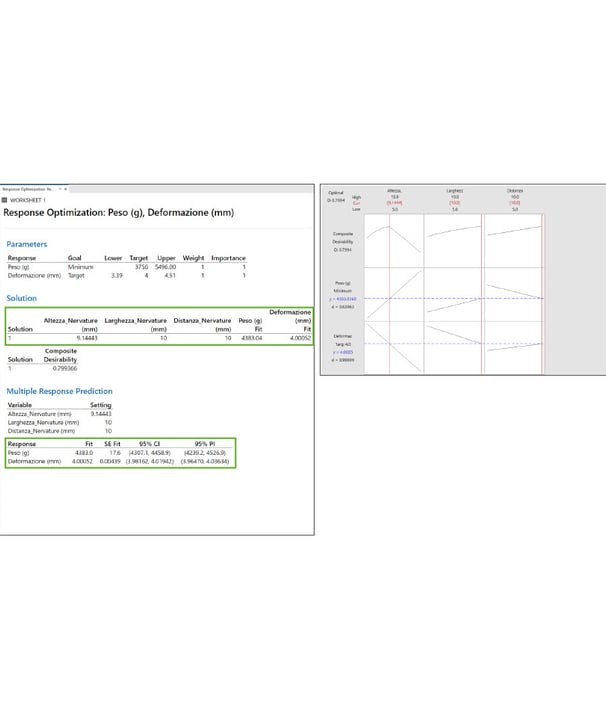
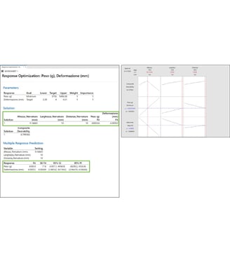
DOE Door Optimisation Results
In this result, the solution obtained by setting the deformation at 4mm and minimising the weight requires the following values to be set:
Rib height = 9.1444mm (9.15mm)
Rib Width = 10mm
Rib spacing = 10mm
gives us a 95% guarantee that the Weight result will be 4383g (between 4.239g and 4.527g). Obviously the deformation of 4mm will be 95% guaranteed between the values 3.9647 and 4.03634
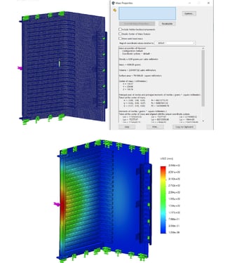
DOE Results FEM Proof
In this proof, setting the values as per the result, re-executing the FEM analysis we find that:
1) Weight is 4.309g instead of 4.383g, 74 grams below the predicted value but within the minimum and maximum prediction values (between 4.239g and 4.527g)
2) Deformation is 3.99mm instead of 4mm, 1 cent below the predicted value but within the prediction values (between 3.96mm and 4.03mm).
This is definitely the most optimal solution for the door, which respecting the 4mm deformation will have the lowest possible weight.
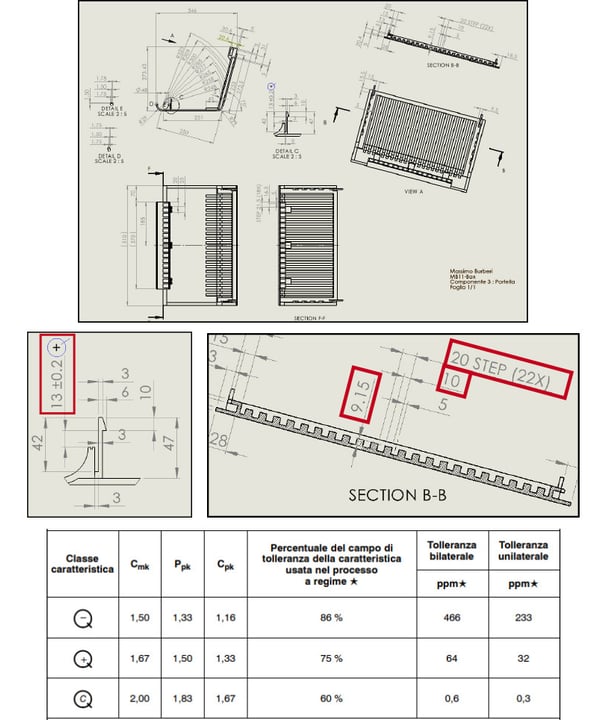
Drawing With Controls
The drawing shows the dimensions of the ribs as taken from the DOE and the critical snapfit tolerance has been highlighted, also indicating to the supplier which Cpk is expected.
Below: the table to be agreed in advance with the supplier.
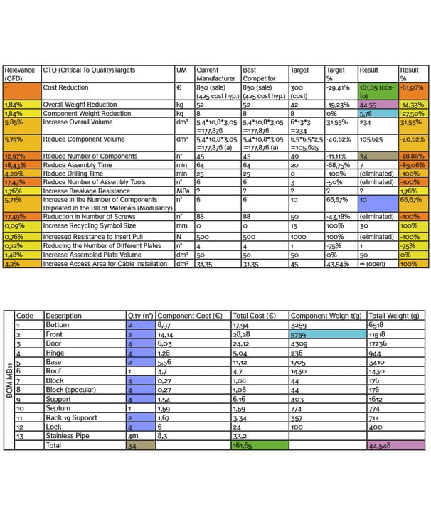
Results
The purpose of showing the final results is to show quantitatively what are the benefits of this redesign.
The (assumed) cost of €425 would drop to €161.65 for a reduction of 62%. (The cost is assumed to be €425 for the analyzes performed and for the sale price of €850 with K=2).
The most important features on which the improvement was focused are highlighted in dark orange: components has been reduced from 45 to 34 (-29%), assembly time was reduced from 64 minutes to 7 minutes (-89%) thanks to snapfits and on-site assembly at the installation site. The assembly toos has been eliminated (-100%) and the number of screw goes from 88 to 0 (-100%) thanks to snapfits.
Modularity has also had a significant increase, going from 6 to 10 components that are repeated in the list (+67%), just as the total volumes have increased (+31%) decreasing the volume of the single component (-40%), facilitating the operator for the installation of the cables offering him open space for the crimping (+100%).


All artworks © Massimo Burberi - All right reserved


